The RIIM Network¶
RIIM Network Attributes¶
Attribute |
Description |
|---|---|
Maximum number of nodes |
1000 (using Border Router Standalone), 900 (using regular Border Router) |
Maximum number of neighbors per node |
32 (for Border Router), 128 (for Mesh Routers) |
Radio bitrate |
Platform selectable: 50kbps or 150kbps |
Medium Access Protocol |
Platform selectable: Single Channel or TSCH |
Frequency bands |
Sub 1GHz: 868 MHz band or 915 MHz band |
Output power |
Module dependent: 14 dBm (Regular power), 27 dBm (High power) |
Joining¶
Child nodes joins the network automatically if they’re allowed; there is no explicit “join” sequence that must be executed. The following list shows what criteria is used to allow joining of a node into a RIIM Network:
PAN ID must be the same for all nodes or set to 0xFFFF (join all)
RF Channel must be the same for all nodes if using Single Channel
Frequency band must be the same for all nodes
Network key must be the same for all nodes
Note
RIIM version 1.1.0 and prior didn’t enable LLSEC.
Join All using PAN ID 0xFFFF¶
If the PAN ID of a node is set to 0xFFFF, it can join any other RIIM network, given that criterias 2-4 above are also fulfilled. This is useful in cases where an already deployed RIIM network has an unknown PAN ID. It can also be used to implement fallback soultions in case a border router or child node goes offline. The join sequence would be:
It’s up to the application to then choose to stay in the network (if it’s the right one) or maybe try again if it’s the wrong one. One possible solution is to have a CoAP resource on the Border router called Open. Is it set to 1 (TRUE) it’s the correct network. If it’s 0(FALSE) then rescan for network again.
Border Router Connection¶
The border router has 3 main functions:
Function as a regular node with support for ICI applications
Function as the Border Router for the RIIM Network.
Function as the connection to an external network
1 and 2 is implicitly supported and autonomous. Connection to an external network will require some configuration. If you are using the Radiocrafts RIIM Border Router, Ethernet works out-of-the box. If you are to develop your own regular Border Router based on the RC18xx-IPM module, and want to use Ethernet, you must connect the SPI bus to a Microchip ENC28j60 which is natively supported by the module.
Note
If you are using your own board without ENC28j60 (Ethernet/LAN connector), you must use the Standalone Border Router platform.
SLIP¶
The Standalone Border Router platform supports SLIP, which is basically IPv6 over serial line (UART). This can be used to connect the Border Router to an SBC, for instance a Raspberry PI, and have full IPv6 addressing capabilities. Radiocrafts provides example setup for this at Github: https://github.com/radiocrafts/RIIM_SLIP_Example
Note
Starting with RIIM version 4.1.0, SLIP now automatically sets the IPv6 prefix of all nodes to the prefix used in the TUN device that is connected to the SLIP. Earlier, the prefix was always an ULA address (Basically FD00::), but now the user can set it arbitrarily using the tunslip command. This eases network setup and routing.
External Node Addressing Using Ethernet and IPv4¶
Each node is assigned a port number on the Border Router Ethernet connection. For the Border Router, this port number is 10000. All communication is treated as CoAP messages.
Frequency and output power¶
The RIIM mesh network is available in these frequency bands:
Frequency |
Location |
|---|---|
863 - 870 MHz |
Europe (referred to as the 868 MHz band) |
865.125 - 866.725 MHz |
India |
902 - 928 MHz |
FCC (US) (referred to as the 915 MHz band) |
915 - 928 MHz |
Australia (referred to as the 920 MHz band) |
918.8 - 921.8 MHz |
Vietnam |
Future variants may also include 433 MHz and 2.4 GHz.
All bands support 50 kb/s data rate. For single channel mode it’s recommended to use the 868 band and the 915 MHz band. These support 34 channels in the 868 MHz band and 129 channels in the 915 MHz band. The channel number corresponds to the numbering in IEEE802.15.5g. The dedicated bands for India, Australia/New Zealand and Vietnam should be used in TSCH mode. Number of channels used for frequency hopping is shown below:
TSCH mode |
Number of hopping channels |
AFA |
|---|---|---|
868 MHz band (EU/CE) |
16 |
Yes |
915 MHz band (US/FCC) |
50 |
No |
920 MHz band (AU/NZ) |
20 |
No |
865-868 MHz (India) |
9 |
Yes |
918-921 MHz (Vietnam) |
16 |
Yes |
For both frequency bands, high power modules with up to 27 dBm are available - RC1882HP-IPM and RC1892HP-IPM. These give extended range due to higher transmitted output power, better sensitivity and better interference robustness (for example vs. 4G/5G base stations) with SAW filter.
Connection to the Internet and Cloud/Server Solutions¶
As all nodes have their own IPv6 address, they can be a part of the internet just like any other internet connected device. Basically, they can address anything, as well as being addressed by anything. Key network (external side/ethernet) parameters are listed in the following table:
Parameter |
Value |
|---|---|
Application layer protocol |
CoAP (without DTLS) or CoAPs (with DTLS) |
Transport protocol |
UDP |
Transport layer ports |
Depending on which node to access. See Custom ICI sequence . |
IP addressing |
IPv4 externally using Ethernet. Automatically using DHCP if available |
Internet protocols |
IPv4 (Ethernet). IPv6 (Internally and SLIP) |
Link MAC/PHY |
10BASE-T Ethernet when using RIIM Border Router and
Microchip ENC28j60 based networking.
UART when using SLIP
|
However, issues with IPv4 translation, firewalls, UDP connections, filters etc. can introduce problems to the flow of data. The most common problems and solutions are described later in this document.
The figure below shows a typical setup for a RIIM deployment.
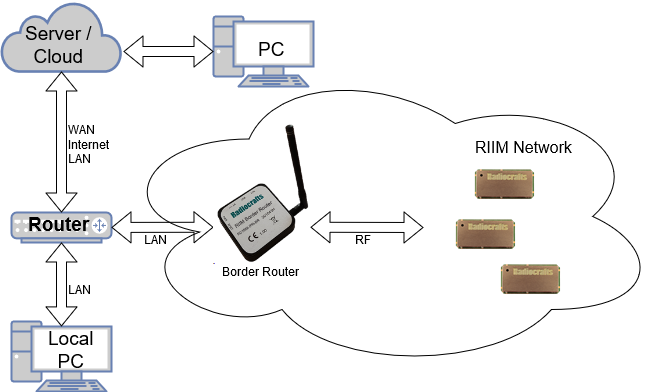
Typical RIIM Deployment¶
In this example, all the nodes in the RIIM Network (including the Border Router) needs to be accessible from the server/cloud, and vice versa. The obvious problem is that the RIIM Network doesn’t know the IP address of the server, and the server doesn’t know the IP address of the RIIM Network. The task of exchanging addresses might be non-trivial, and the following list describes some of the problems and solutions:
- Depending on the firewall policies, “stray” UDP packets from outside the LAN may be stopped by the router, which means that the exchange of addresses can’t be initiated from the outside cloud/server. Possible solutions:
Initiate the exchange from inside the LAN
Configure the router/firewall
- Router may not keep traffic open for incoming UDP packets forever. Possible solutions:
Nodes may need to periodically send packets to server and vice versa to keep channels open
Configure the router/firewall
- The address of the Border Router is unknown after it has been connected to the LAN. Possible solutions:
The address of the Border Router can be dumped on the UART if the ICI application calls the “Debug.printSetup()”-function
The address may be extracted from one of the address tables in the LAN router, depending on the router type and setup.
Using ICI, the Border Router can itself send a message to a known address upon power up. The address can be hardcoded in the ICI application or stored in non-volatile memory.
When using SLIP, the Linux TUN device itself can be used for commissioning. Radiocrafts provide such an example on GitHub : https://github.com/radiocrafts/RIIM_SLIP_Example .
Given the above points, there are several ways to exchange the addresses between the server and the RIIM Network. The following chapters discusses some of them.
Hardcoding the server address using ICI¶
If the address of the server is known, it can be hardcoded into the module in the ICI application. Beware that the server address can’t change permanently unless you update the ICI application. However, firmware upgrade is easy through OTA. See the SDK documentation for details on setting the server address.
Using a PC/SBC on the LAN¶
Using a local PC to provide the RIIM Network with the address to the cloud/server ensures that the address exchange is initiated from the LAN. This works the following way:
The Border Router is provided with the address to a server and the name of a CoAP resource on that server.
The Border Router sends a CoAP message to the server with some identification. This can for instance be the IP address.
When the server sends its ACK response, the sequence is complete. The server now has the node IP and the node has the server address.
Custom ICI sequence¶
The ICI application gives virtually infinite possibilities regarding custom commissioning sequences. Modules with the EEPROM allows for the ICI application to use on-board non-volatile memory that can be used by the application to store/update the server address(es).
Protocol gateway¶
Even though RIIM is end-to-end IP capable, one can also add a protocol gateway to enable other transport protocols, as seen in Figure 4. The gateway can convert UDP/DTLS/COAP to TCP/TLS/MQTT(HTTP) and vice versa. Such a solution is more complex and challenging to set up, while it gives the advantage that the two protocol suites can be optimized for different network properties. A protocol gateway can easily be implemented on a standard Linux computer using open source conversion tools.
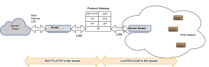
Protocol Gateway Concept¶
Out of the box solution¶
For complete out-of-the-box solutions, see our development kit and our stand-alone RIIM Border Router Concept.
Accessing RIIM Nodes Directly From Outside Using IPv4¶
Even if the address of a child node is known, some prerequisites must be met to allow direct accessing. The main problem arises as a translation is needed between the LAN IPv4 to the IPv6 used in the RIIM Network. To allow direct access, the Border Router implements a NAT which assigns a port number to a RIIM Network node. The NAT in RIIM platforms prior to 1.1.0 is dynamic and is initially empty. On later versions, the child nodes are assigned port numbers in increasing order according to their index in the network topology. Therefore, child node 1 is assigned port number 10001, child node 2 is assigned port number 10002 etc. To retrieve the indexes, you must read out the topology (the DAG). The index is given by the place of the node in the DAG list. See chapter Get the RIIM Network Topology for details. The border router starts with port number 10000.
Warning
The DAG is dynamic and may change when the RIIM network (re)forms. Therefore, the port indexes will also be dynamic.
Note
Port numbers 10001…. only works when accessing child nodes from the outside (LAN). The replies will come from a NAT64 dynamically assigned port.
If a child node first send a packet out onto the LAN, a port is dynamically assigned to the node and it can be accessed using the Border Router IPv4 address and the assigned port. The Border Router supports up to 32 custom NAT entries at any one time. The external application need to parse the UDP packet sent from the Border Router to figure out the assigned port number.
Note that transmission TO the node can also assign a different NAT64 port if any source parameter is different, such as the source port or address.
A packet coming from outside can be sent to the Border Router instead of directly to a RIIM Network child node. The Border Router will function as a hub and could then run an ICI application that resends the packet to the correct node. For instance, part of the payload sent to the Border Router could be the IPv6 address of the node, or it could be an index.
Note
If using IPv4, Radiocrafts recommends using the border router as a hub as described in the last bullet point above as the Border Router port is static and the need for advanced network manipulation will be minimized
Border Router External IP Address Assignment¶
The Border Router supports assignment of an IPv4 address to the Border Router. This makes it accessible to the local network via ethernet. The address is set when the user starts the Border Router, as exemplified in the following code snippet: Example: ICI code
const uint8_t ipv4_address[4]={0,0,0,0};
const uint8_t ipv4_netmask[4]={255,255,255,0};
const uint8_t ipv4_gateway[4]={192,168,1,100};

RIIM_SETUP()
{
    Network.startBorderRouter(NULL, ipv4_address, ipv4_netmask, ipv4_gateway);

    return UAPI_OK;
}
Example 1. Setup of Border Router with a DHCP provided IPv4 address
Note
If DHCP is enabled on the network the IP address given by the DHCP server is used regardless of explicitly set addresses in Network.startBorderRouter
RIIM Network Address Assignment¶
IP addresses for the Child nodes are automatically managed. The IPv6 (global) prefix (first 64 bits) is the same as for the Border Router, and the IID (last 64 bits) is created based on the IEEE address (EUI64) in the module itself. Therefore, for the Child nodes, you can’t change their IP addresses. However, you can read it out, and all Child nodes also knows the address of the Border Router.
Security¶
Security is a key element in any wireless network. RIIM offers two levels of encryption and authentication.
In the wireless network there is a link-layer security that encrypts each packet at the MAC layer. This ensures that only nodes with the correct link-layer encryption key can join the network or listen to traffic in the network. This link layer security is also used for network management packets, so an eavesdropper can’t decode management traffic. Link layer security use a shared key for the entire wireless network and is therefore often referred to as network security.
Link layer security encrypts the data within the mesh network, but not outside. In order to protect data that’s sent or received from the internet, RIIM provides support for DTLS, a security protocol which is part of the internet protocol suite made by IETF https://en.wikipedia.org/wiki/Datagram_Transport_Layer_Security.
DTLS ensure end-to-end UDP packet encryption. Through DTLS there is a unique application security key for each device. Since DTLS include negotiation between the end points, DTLS can’t be combined with multicast.
Multicasts¶
Regular Multicast¶
Multicast is an efficient way to broadcast data to many or all devices. The multicast in RIIM is based on the IETF standard MPL, which include both flooding the network with retransmissions and a control protocol for syncing between neighbors and requesting missing multicast packets. This broadcast technique is more robust compared to a simple fire-and-forget strategy.
One-hop Multicast¶
RIIM also provides a local multicast called link-local or one-hop multicast. This sends a multicast packet to all nodes within listening range but doesn’t traverse the network. This is useful if only nearby nodes need to get the packet and has the benefit of reducing network traffic.
A typical use case for the one-hop multicast is that one node in the network detect an event that the other nodes in the neighbourhood should be aware of. For example park-lights that detect a jogger and wants to tell nearby lights to turn on.
Network Data Packets¶
The network packets conform to the IEEE802.15.4g standard. They use IPv6 addressing as defined by 6LoWPAN. Every node will have its own unique address, which enables every node to be uniquely addressed from across the internet. The Border Router provides the translation between 6LoWPAN messages and regular IP messages. No additional Border Router functionality is needed as these messages can be sent directly onto the internet. Some physical connection is of course needed, and the RC18xx-IPM already supports ethernet via SPI and Microchip ENC28j60. Additionally, the RC18xx-IPM supports a SLIP interface since SDK version 2.0.0.
The transport layer is UDP. It’s possible to send packets using only UDP without any application layer and with custom payload. This will save packet overhead and allow for a simpler “fire and forget” way of transmission compared to also using application layer. CoAP messages using User Datagram Protocol (UDP) can be used to transmit the actual data payload, optionally with encryption using DTLS. Each node can only be connected to one CoAP server at a time for client operations. The node’s CoAP resources can be accessed by multiple clients, as long as not DTLS is used.
CoAP adds to the header size but enables addressing similar to HTTP. It may require a response to ensure delivery of the packet. It’s also possible to send a CoAP message without asking for a response, in which case multicast and more power efficient nodes are supported. Multicast is supported for bare UDP packets and CoAP without response.
Link Layer Security (LLSEC) is implemented and encrypts all packets in the network using the same pre-shared key.
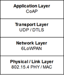
Stack Layers¶
Data packet overhead¶
For details on the packet see the IEEE 802.15.4 standard.
Packet sent as a regular CoAP request is shown below. Using only UDP will remove the CoAP specific bytes from the header.
SHR |
PHR |
PSDU |
|||||||
|---|---|---|---|---|---|---|---|---|---|
Pre-
amble
|
SFD |
Reserved |
Length |
MAC
Header
|
MAC Payload |
MAC
footer
FCS
|
|||
4B |
2B |
5bit |
11bit |
9B |
15B |
7B |
11B § |
X |
2B |
IP
header
|
UDP
header
|
CoAP
header
|
CoAP
object
|
||||||
Note
§ The CoAP header includes the resource name used in the URI.
Example:
\\192.168.0.14\log\
    192.168.0.14 is an IPv4 address we are sending to.
    log is the resource the CoAP request is sent to.
With a resource name of 3 characters the CoAP header becomes 11 bytes.
A 12 character resource name gives 20 bytes CoAP header.
The overhead in the above example is 52 bytes.
The IP header in this example sends a packet to its neighbor. Source addressing adds 2 extra bytes per hop, so sending to a node 10 hops away gives 20 bytes extra overhead.
Link/transmission robustness¶
Sometimes, it might be better to ignore nodes with a low RSSI. There can be several reasons for this:
It can be better to insert a new mesh router than having a weak and unstable link. The link could also be influenced by external dynamic factors, for example a car parking between the nodes
In dense networks, many nodes can hear each other. This can lead to congestion and fill up the nodes’ memory. This, in turn, will lead to network instability
Using the setRobustnessFactor function in the Network API might help these issues. The following example shows how to ignore all packages with an RSSI less than -80 dBm.
Network.setRobustnessFactor(-80);