Network Timing and Latency
Single channel latency
The latency in the single channel variant of RIIM is low, but as with networks in general; non-deterministic. The radio includes listen-before-talk to increase robustness and reduce interference. Packet loss and automatic retransmission will cause extra delay. Following is a method to calculate estimated latency.
The RF data rate is 50 kb/s so 1 byte has an airtime of 0.16 ms. Based on the packet overhead example given above, and 10 byte CoAP payload, the total RF airtime is 62 bytes x 0.16 ms = 9.92 ms.
The acknowledgment typically comes within 1ms.
The latency in a multihop network is given by
LatencyOneWay= TxTime+AckTime+(NumberOfHops-1)*(RoutingProcessingTime+TxTime+AckTime)
To calculate the complete two-way CoAP request and response this latency must be multiplied by 2. The processing time at the CoAP server end must also be considered.
LatencyTwoWay= 2*( TxTime+AckTime+(NumberOfHops-1)*(RoutingProcessingTime+TxTime+AckTime))+CoapResponseTime
The routing processing time is typically 45 ms. A typical CoAP server response is 40 ms.
This will vary depending on what other tasks the device is performing.
Example 1: Sending 10 bytes user data one way to a device 3 hops away
Sending 10 bytes user data to a device 3 hops away.

Latency one way = 9.92ms + 1ms + (3 -1 )(45 ms + 9.92ms+1ms) = 122.76 ms
Example 2: Sending 60 bytes user data to a device 1 hop away and get a response back
Latency two way = 2x(16.32ms + 1ms + (1 -1 )(45 ms + 9.92ms+1ms))+ 40ms = 79 ms
Effect of packet loss:
Packet loss will create additional delay as packet retransmission must be added. A rule of thumb is that one retransmission of a lost packet typically takes between 40-60 ms. Therefore 50 ms delay is a good estimate.
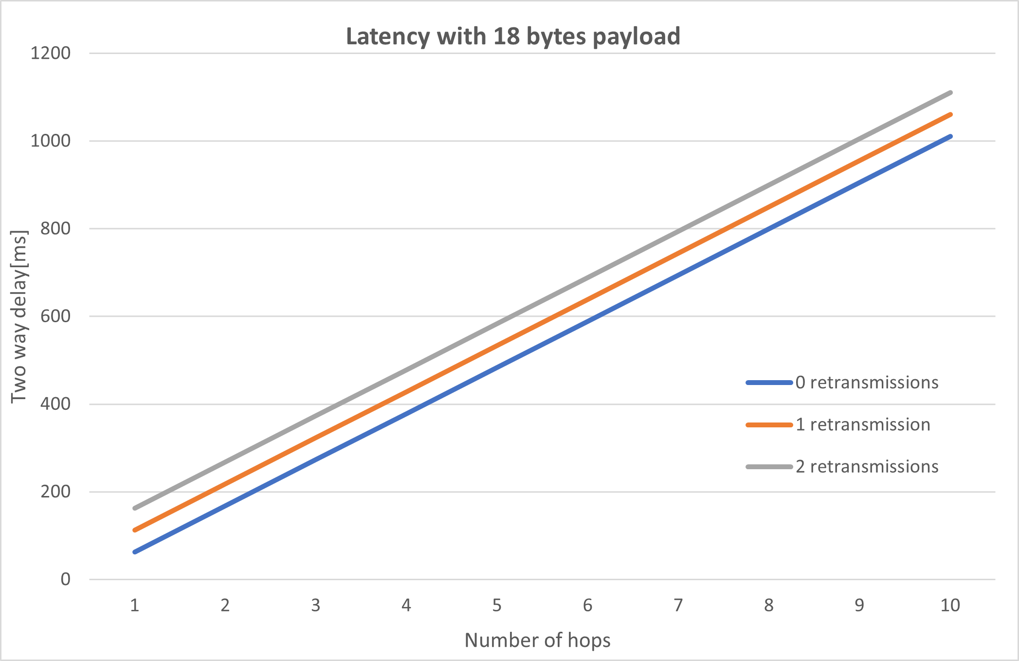
Typical Latency for Request/Response
TSCH latency
The TSCH variant of RIIM has a higher latency than single channel since it must wait for the right timeslot before it can transmit or receive. In ideal circumstances, a node waits 340 ms on average for the next timeslot. The length of a timeslot is 40 ms, which includes packet transmission and an optional acknowledgement packet. This is independent of payload size. From this, the average latency in a multihop network is given by
MeanLatencyOneWay = TimeUntilNextTimeslot+TimeslotLength+(NumberOfHops-1)*
(RoutingProcessingTime+TimeUntilNextTimeslot+TimeslotLength) =

(TimeUntilNexTimeslot+TimeslotLength+RoutingProcesingTime)*NumberOfHops-RoutingProcessingTime
From this we can calculate the latency for the previous (Single Channel) example:
Example 1: Sending 10 bytes user data one way to a device 3 hops away
Latency one way = (340 ms + 40 ms + 45 ms) * 3 - 45 = 1230 ms
Example 2: Sending 60 bytes user data to a device 1 hop away and get a response back
Latency two way = 2 * ((340 ms + 40 ms + 45 ms) * 1 - 45 ms) + 40 ms = 800 ms
This is under ideal circumstances. A packet might be delayed because of retransmission during packet loss with an exponential back-off feature that will increase the delay significantly, or delay because of other packets with higher priority in the packet queue. This will increase the latency, and actual measurements has shown latencies of 570 ms per hop with a 97 % link-layer packet delivery rate, and 1055 ms per hop with a 88.5 % link-layer packet delivery rate.
Network Throughput
To maximize throughput there are several effects that need to be taken into consideration.
One by one transmission.
-If all devices are transmitting at the same time, more interference and higher packet loss will be seen
Maximize data length to minimize overhead. Sending 20 and 20 bytes is more efficient than sending one and one byte.
Send next message based on CoAP response. If not the CoAP queue will be filled up and the performance won’t be stable.
If no response is needed, consider using CoAP without response or raw UDP
If all devices in the network are sending data, the border router will be the limiting factor. The simultaneous throughput from hundreds of devices in a large network will in the order of a few bits/second per device.
Single channel throughput
Based on the above system, the throughput can be estimated based on the latency.
Example 3: Based on example 2 above the latency with one hop is 79ms/64 bytes. If we add a processing time of 30 ms for sending the next packet (receiving CoAP response, parse and prepare next packet) we get 64 bytes/116 ms = 4.7 kb/s.
This is based on no packet errors, one hop and one device transmitting, so this is the maximal theoretical throughput.
The theoretical limit for throughput for different number of hops and different CoAP payloads are given in Figure 8.
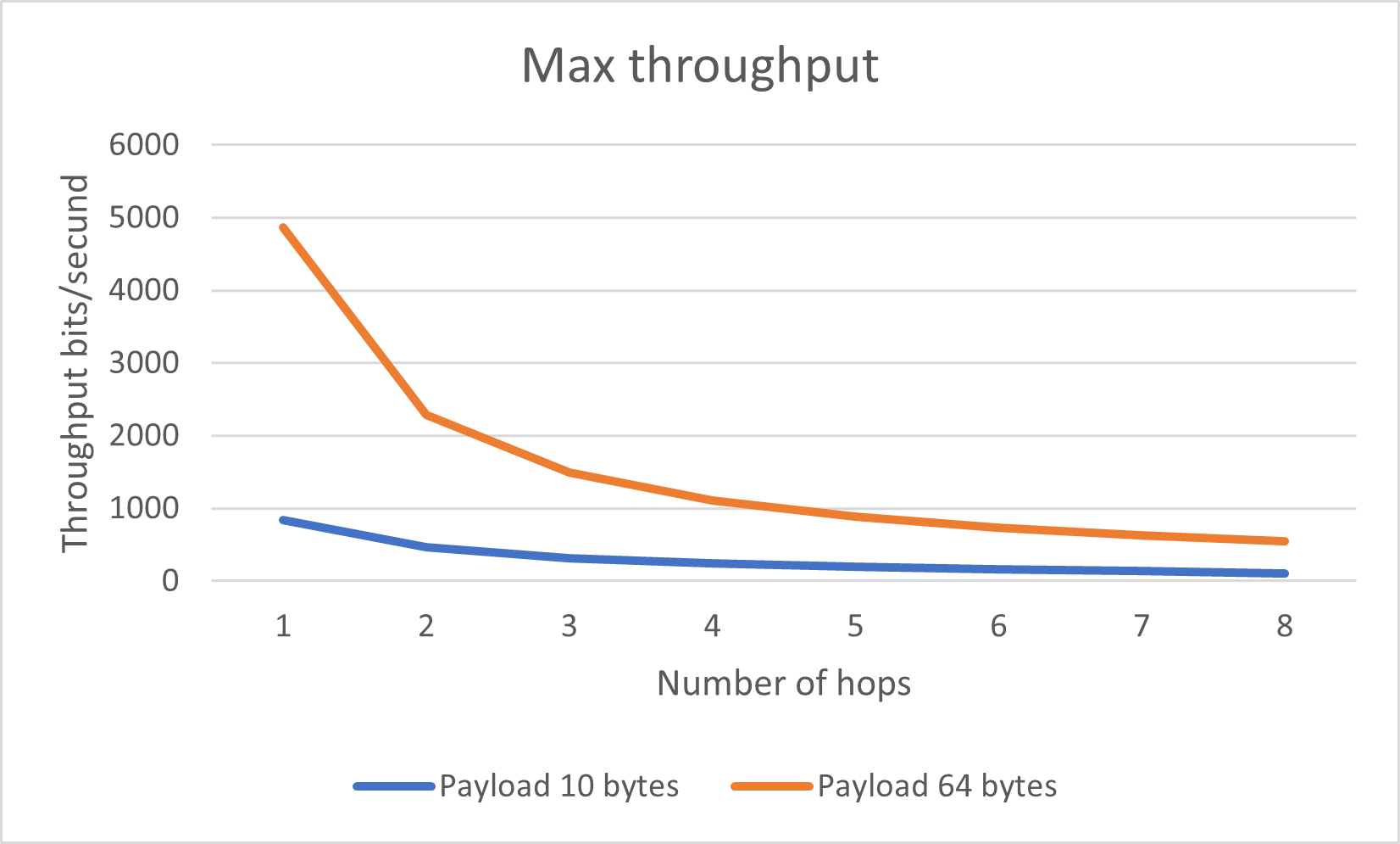
Max Throughput
TSCH throughput
A TSCH node has an opportunity to send a radio packet every 680 ms which, with for exmple a 64 byte payload, gives a maximum throughput of 753 bits per second. The maximum usable payload size per packet depends on things like the protocols used, the number of hops to the destination and if encryption is enabled.
Network Congestion
A RIIM network share a common media (RF channels) which is a limited resource. Competing nodes (sending on the same channel, or within the same timeframe) might lose packets due to packet collision.
In a RIIM network packets are stored and forwarded in the mesh routers with finite storage space. Hence with many nodes in a network sending a lot of data there is a possibility of data congestion in the network. This can be avoided by giving thought to the network and system design. Following are some guidelines for scaling RIIM networks.
Unicast data to the border router
The Border Router can in theory receive about 30 packets per second (in ideal circumstances, this is unrealistic in real deployments). The real throughput will vary depending on:
Network topology
Network density (How many nodes the border router can talk to)
Single channel CSMA vs. TSCH
Traffic pattern (N nodes sending P packets vs one node sending N*P packets)
The expected throughput is in the range 3-10 packets per second. This means that a network with 1000 nodes must have a strict limitation on how often data can be sent from each node. In large network it’s important to distribute the unicast messages in time. If all 1000 nodes in a large network is “synchronised” with their transmissions, the incoming packet rate will periodically exceed the capacity, resulting in increased packet loss. Therefore, it’s important to add random delays for start-up and packet transmission in large networks.
Unicast data from the border router
This follows the same limitation as unicast data to the border router. In addition, there is a limitation in the 868 MHz band in Europe for max TX duty cycle that can limit this even more.
Multicast data from the border router
Multicast messages traverse the network slower, due to retransmission. The border router can send two or more multicasts directly after one another, but then they will overlap in time when traversing the network. This will increase the probability of packet collision. How often a multicast message can be sent depends on the network size and the tuning of MPL that can be done. If to many messages are in the network at the same time the probability of lost and repeated multicast messages increases.