Quickstart
Make sure you have the SDK and requisites installed, see SDK Setup for details.
Building, uploading and running ICI applications
To run your first application, this guide will show you how to:
Build and upload the ICI application using an existing example
Building and Uploading Using VSCode
The SDK provides a workspace file and setup for compilation and uploading ICI applications in Microsoft Visual Studio Code. To open the SDK in VSCode, open the file RIIM.code-workspace present at the top level of the SDK.
You can safely ignore and close these popups in VSCode if they appear:
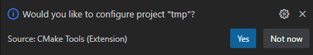
Click “Not now” if this appears
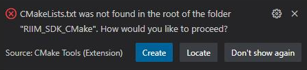
Close or select “Don’t show again” if it appears
To build an ICI application, simply select the file you want to compile in the leftmost EXPLORER window and press SHIFT-CTRL-B. This builds whatever file you have selected and is open in the editor. When building is finished, you are prompted for the port number at the very top of VSCode
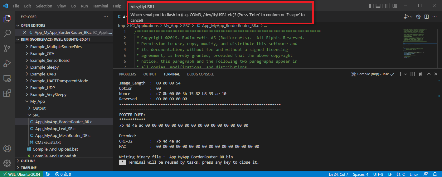
VSCode prompts the user for which serial port to use
Here you enter the port your RIIM module is connected to, for instance COM3 or /dev/ttyUSB0. Or just press ENTER to exit without uploading anything.
If you have provided a serial port and the module is not in bootloader mode, you will then be prompted to enter bootloader mode by pressing RESET on the board.
VSCode prompts the user for entering bootloader mode.
Finally, Bootloader Status: Success should be printed in the VSCode terminal window:
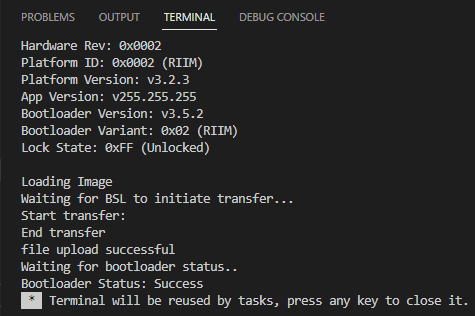
Printout after successful build and upload using VSCode
Now you can reset the board and your application will start.
Building and Uploading Using Scripts
To build and upload your first ICI application, go to the folder ICI_Applications/My_App and execute Compile_And_Upload.bat (Windows) or Compile_And_Upload.sh (Linux). Execution can be done by double-clicking on the file from the file explorer, or by execution from the command line.
This will take the source files provided in the SDK and create image files that are ready to be uploaded to the modules that are mounted on the boards in the Development Kit.
After the compilation and image generation is finished, you’ll end up with this message:
Writing binary file :  App_MyApp_BorderRouter_BR.bin
Enter port (or enter to abort) []:
Here you will have to type in the name of the serial port / COM-port that your board is connected to. See How Do I Find My UART Port on Windows? for details on how to determine which COM port to use. Remember also to type in the whole COM port name, not just the number. For instance, use COM23 instead of 23. For Linux, the port will be a ttyUSB port, for instance dev/ttyUSB0. If you want to just build the application without uploading, you can simply press ENTER to skip uploading.
The filenames themselves describes what board the image is to be uploaded to. See Example Structure and Naming Conventions for a description on the naming convention used. For example, “App_MyApp_Leaf_SB” means that this image should be uploaded to the Sensor Board.
Note
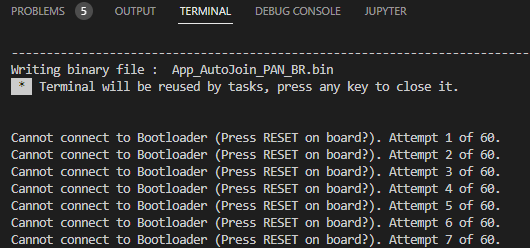
Remember to reset the board if the following message appears:
Cannot connect to Bootloader (Press RESET on board?). Attempt 1 of 10.
Enter port (or enter to abort) []: /dev/ttyUSB0
……………
Loading Image
Waiting for Bootloader to initiate transfer...
Start transfer:
End transfer
file upload successful
Waiting for bootloader status..
Bootloader Status: Success


----------------------------------------------
ALL DONE!
----------------------------------------------
Press enter to continue
You need to repeat this compile and upload process for each of the boards in the development kit. Pay attention so that the right ICI application is uploaded on the right board.
When finished, you need to reset the boards you just uploaded the image to. The reset button is located on the side of the board. The modules on your boards are now programmed with the ICI applications that are needed to connect the boards and start your RIIM network. Descriptions of the examples are in the README-files in the Example-directories.
Compile Using CMake
Using CMake describes how to use CMake directly. Also, see the Compile_And_Upload file located in /ICI_Applications/Example…. for example on how to use CMake.
Observing the Output
The ICI application simply starts the module as a node and prints out a greeting + configuration. If you open the UART (COM* / ttyUSB*) in a terminal program using a baudrate of 115200 and reset the board, you should see something like this message when the board is started (reset):
~/RIIM_SDK/ICI_Applications/My_App$ microcom -s 115200 -p /dev/ttyUSB0 connected to /dev/ttyUSB0
Escape character: Ctrl-\
Type the escape character followed by c to get to the menu or q to quit
Starting RIIM Node
# RIIM node configuration:
# - Application Version : 0xffffffff
# - Hardware ID : 0x0000
# - Hardware Version : 0x0000
# - Platform ID : 0x0002
# - Platform Version : 0x00000923
# - Platform Description : RIIM_NODETYPE_MeshRouter
# - MAC Address : 0xf7aabc1c004b1200
# - PAN ID: 0x9812
# - Node ID: 43767
# - Link-layer address: aaf7
# - Local IPv6 address: fe80:0000:0000:0000:0000:00ff:fe00:aaf7:
# - Global IPv6 address: 4c46:0101:0100:0000:0000:0000:0000:0200:
# - Reset code: 0x00000001
The way forward
Now you are ready to start testing. A nice place to start can be to edit the file ICI_Applications/My_App/SRC/App_MyApp_MeshRouter_DB.c and see that your changes is reflected in the executing code.
Be sure to go to www.radiocrafts.com for the latest SDK, documentation and knowledge.