The RIIM™ Parts and Tools
The RIIM™ Parts describe the different parts you can use to build your RIIM™ Network, and the RIIM™ Tools are developed to support a project with fast to market requirements. We strive to make the tools easy to use and make the documentation easy to follow.
The RIIM™ Parts
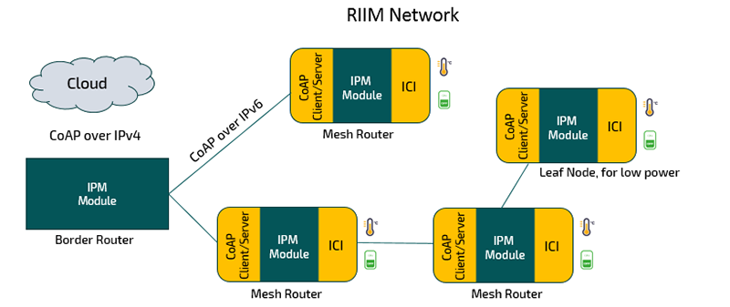
The RIIM™ Network is built using some or all of the following:
The RIIM™ Module
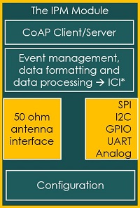
The IPM Module is the core of the network nodes and supports the complete RIIM network.
The RIIM™ module is a complete, very low power-consuming IEEE802.15.4 g/e RF node with a 50 ohm antenna interface. It can connect to several PCB buses and interface to any sensor or control unit via the ICI interface.
The module can be configured for 868 MHz or 915 MHz operation, and the Power output level can be set.
Customer configurations including the parts that are controlled by firmware; The local data management, formatting and processing, and the configuration of the module, are programmed by the customer in a high-level C language and loaded in the module at boot. Radiocrafts has developed a unique framework to make the code very simple to develop. The framework is called ICI, pronounced [i:zi].
Visit Radiocrafts’ GitHub page to explore sample codes for RIIM applications and features.
Also visit Radiocrafts’ Online RIIM Documentation Library to read more about RIIM features, the RIIM development tools, and more.
The module includes a CoAP client/server that enables direct IP communication with the node.
The module comes in three different hardware options:
- RC1882CEF-IPM has 14 dBm max output
- RC1882HPCF-IPM has 27 dBm max output for 868 MHz
- RC1892HPCF-IPM has 27 dBm max output for 915 MHz
Output Power | Frequency | Range LOS | Range in Urban Environment | |
RC1882CEF-IPM | 14 dBm | 868/915 MHz | 5 km | 200 m |
RC1882HPCF-IPM | 27 dBm | 868 MHz | 20 km | 700 m |
RC1892HPCF-IPM | 27 dBm | 915 MHz | 20 km | 700 m |
RIIM can also be configured in two different data rates:
- 50 kbps mode
- 150 kbps mode
The module can be configured in three different modes depending on its’ intended role in the network:
- Border Router – The Border Router is the root of the network and connects the RIIM network to the outside world.
- Mesh Router – Can forward data to and from its parent nodes to its child nodes. The mesh router nodes collect and forwards data to local sensors and actuators. They also serve to extend the network if needed. TSCH enables battery operated mesh routers. This is due to the radios can be shut down in period when there is no packet to send and no incoming packet expected.
- Leaf node – sits at the end of the network and has no mesh routing functionality. It collects and forwards data to and from local sensors and actuators up to its parent node. The Leaf node can be put to sleep for very low power consumption (4.7 uA), ideal for battery operated sensor nodes.
The configuration is selected when the module firmware is created and programmed into the module by the bootloader.
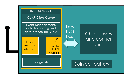
The mesh router and leaf node are child nodes in the RIIM network. The child nodes are the nodes in the network that directly or indirectly connect to the border router are the units where the remote sensors and/or the control unit interfaces are located. The physical hardware is very simple and just needs the following parts:
- The IPM module
- The sensors and units to control connected to the IPM module via a local PCB bus
- A power source, typically a small battery
- The PCB
- An antenna, either an external antenna or a PCB antenna
- The enclosure, the mechanical box
This design is exceptionally simple to actualize for an electronics engineer with some hardware experience. If a PCB antenna is desired, then an RF designer also needs to be involved.
Universal Sensor/Controller Interface
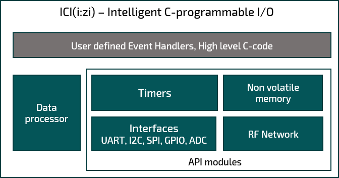
The ICI framework is designed to provide a very simple platform to program any sensor/controller interface in high level C code with simple APIs to access the module’s resources and I/Os. Any sensor/controller that has a hardware interface using I2C, SPI, GPIO or UART can be interfaced to via the ICI framework.
The ICI [i:zi]
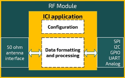
ICI offers the possibility to implement Mist Computing algorithms and to create an interface to any sensor/controller. All programming is done in high level C coding and uses API modules that remove the need to manage the chip resources. Please click here for more details.
An ICI application is triggered by events, such as data coming in or a timer event, which once triggered, performs that task programmed in C, and then it goes to sleep and waits for the next event. The events can be complex such as reaching a threshold or executing the code once a combination of events occurs.
The flexibility of using high level C-code in ICI, means that virtually any sensor and/or control unit can be interfaced to, as long as they can be connected to the local hardware buses. The data can be manipulated on bit level in the ICI application and advanced data processing can be used. This also means that a good ICI application can reduce the data transmission significantly, thereby reducing the power consumption. The limitations are really just limited by the designer’s creativity.
Several of the capabilities of ICI are shown below:
- Updating the code in the field via “over the air upgrades”
- 915 MHz or 868 MHz frequency based on pin information
- Reacting to several sensors, e.g. high temperature and high humidity
- Local data-logging
- Sending pre-defined bit patterns, such as keeping a light blinking in a special way.
- Adaptive sensor reading frequency.
And many, many more.
Visit Radiocrafts’ GitHub page to explore sample codes for RIIM applications and features.
Over The Air (OTA) Firmware Updates
The firmware used in the module can be updated over the air, including the firmware used for ICI. This allows for bug fixes and other updates when the network is deployed. Over the Air (OTA) updates make it possible to update RIIM in the field. This is great for:
- Updating the user defined ICI application
- Uploading new features that come from Radiocrafts
- And bug fixes from Radiocrafts
OTA can save on large costs compared to sending out installation staff to upgrade network nodes with bugs that are already installed in the field, and it can also be used to add or modify the local data processing needed for changes in the environment.
Additionally, with the multicasting features supported by RIIM, the user can send data messages to all nodes in the network at once. This eases situations where you want to send the same message to a lot of nodes at once. This is useful if you want to turn off all lights in an area at once or to update a parameter in the whole network at once. Additional benefits include:
- Reduces duty cycle usage
- Much faster than if the Border Router must address each node individually (unicast)
- The user doesn’t have to know the addresses of all nodes
The RIIM Border Router (to be released)
The RIIM Border Router is a complete CE certified boxed product that will connect to the Internet via an Ethernet interface and CoAP.
The box products are optional in RIIM and intended for customers who prefer not to develop their own hardware for the border router. The alternative is to integrate the IPM module in another hardware box and configure the module as a border router.
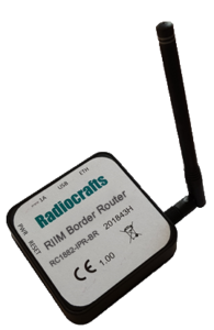
The core of the Border Router is the IPM module configured as a Border Router. The additional blocks are an Ethernet transceiver, a PCB, and the antenna.
The Border Router is orderable in 4 variants, 2 frequency options, 868 MHz and 915 MHz and two Output power options, See the table below.
Frequency | Conducted Power | |
RC1882-RIIM-BR (To be Released) | 868 MHz | 14 dBm |
RC1882HP-RIIM-BR (To be Released) | 868 MHz | 27 dBm |
RC1892-RIIM-BR (To be Released) | 915 MHz | 14 dBm |
RC1892HP-RIIM-BR (To be Released) | 915 MHz | 27 dBm |
Note: The Border Router is soon to be released.
RIIM supports two modes of operation, cloud connectivity over internet and the option to run RIIM as a private network. You can read our application note 33: Set-up RIIM Sensors To The Cloud to learn how to connect RIIM to the cloud.
RIIM is designed to have direct cloud connection using protocols such as IPv6, UDP, CoAP and DTLS. This eliminates the need for a dedicated gateway and offers direct end-to-end IP packet communication with end-to-end security. In addition, RIIM can operate in a local mode where no internet connection is used.
A third use case that is common is to extend RIIM with an edge gateway and then have external cloud connection from the gateway device. This is useful when the user intends to implement some edge-computational functions, thus decreasing latency. It can also be useful in case connection to the cloud is lost.
You can read more about connecting RIIM with an edge gateway in our Application Note 36: RIIM with Edge Gateway
You can also visit Radiocrafts’ GitHub page for a sample code on how to connect a RIIM network to an edge computer.
The RIIM™ Tools
The RIIM™ Tools are developed to support a project with fast to market requirements. We strive to make the tools easy to use and make the documentation easy to follow.
The RIIM SDK
The RIIM SDK supports development of code for the ICI application in the IPM module.
A custom ICI application for wireless sensors or actuators can be quickly and easily developed on the IPM Module. An ICI application is always running on the module on top of the Platform Image, to tailor the modules behaviour to the customers unique requirements. The ICI application is written in a high-level C-language, using a powerful API that is available in the SDK.
The API removes the need for the developer to understand the underlying architecture and resources in the module. An ICI application can typically be done with less than 100 lines of code and within a few hours.
No expertise in wireless networking or device specific knowledge is required.
The RIIM SDK comes with:
- Extensive documentation
- Platform firmware for the RC1882CEF-IPM and RC18x2HPCF-IPM in encrypted binary
- C Libraries
- Build scripts
- Flashing tools
It also comes with several ICI examples with documentation and source code:
- Read temperature and humidity sensor and send data to root node
- Read accelerator and send data to root node
- Read ADC and send data to root node
- OTA update example
- 6LoWPAN to IPv4 network
- Large network example
- UART example
- Interfacing all sensors on the sensor board
- Sleepy Node example
Read more about ICI examples using the RIIM SDK here.
You can also visit Radiocrafts’ GitHub page to explore sample codes for RIIM applications and features.
Also visit Radiocrafts’ Online RIIM Documentation Library to read more about the RIIM SDK including User Manuals and Quick Start Guides.
The RIIM™ Network Dashboard

Installing a reliable mesh network requires an understanding of the radio link quality between the nodes. You need to ensure that the nodes are located such that there is some margin in the signal to noise ratio, and such that additional noise or obstructions of the signal path do not break connections that are important for the network functionality.
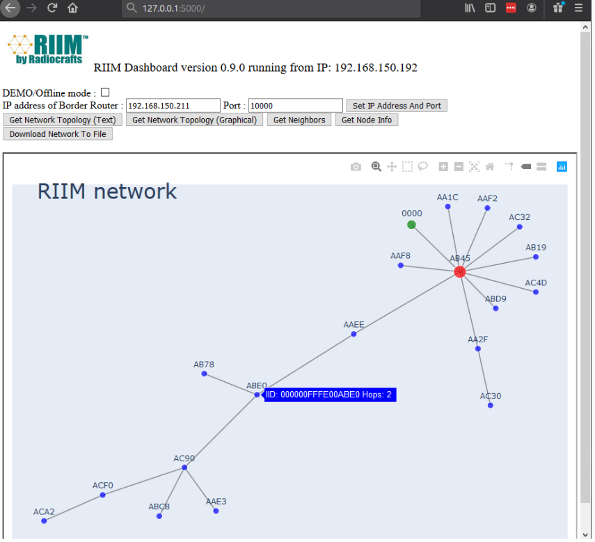
Radiocrafts has created a tool to analyse the network quality called The RIIM Dashboard, a tool which greatly simplifies the installation and operation of a wireless mesh network to ensure that every single node has the fullest and most effective connectivity possible in the network.
The RIIM Dashboard allows the user to monitor the link quality during installation and also during operation.
It can also be used to run network diagnostics. You can see the link strengths between the nodes in the network using easy to use interactive graphics.
The RIIM Dashboard is a stand-alone application used to analyse and monitor an active RIIM network, and it is capable of:
- Retrieving the RIIM network topology
- Graphically and interactively showing the network
- Retrieving the neighbour table of the Border Router, showing the RSSI of the links to the other nodes
- Retrieving the Node information of the Border Router, including the IP addresses and PAN ID
- Saving the current network state to CSV files for later analysis in e.g. MS Excel
- Connecting to any IPv4 address and Port
- Added RSSI readout and network traversal
- Added configurable link coloring in interactive mode
The RIIM Dashboard is interactive and runs in a web browser as it creates its own local web server. It can also be run in OFFLINE / DEMO mode if it is not connected to a Border Router.
The RIIM™ Development Kit
The RIIM™ development kit is designed to make it easy for the user to evaluate the RIIM network and to run preloaded ICI application or to make a user specific ICI application with minimal time and effort.
It includes all hardware needed to run a small RIIM™ network from a PC. This allows the customer to test the network capabilities with minimum development resources needed. This is ideal for a first range test in a customer environment.
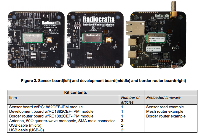
The RIIM™ development kit includes three boards with antennas, power supplies, as well as a USB cable for connection to a PC:
- A RIIM Border Router Board, a development board with an IPM module
- A RIIM Development Board (Mesh Router Board), a development board with an IPM module.
- A RIIM Sensor Board, a board with an IPM module and 7 industrial sensors.
Frequency | Output Power | |
RC1882-RIIM-DK | 868/915 MHz | 14 dBm |
RC1882HP-RIIM-DK | 868 MHz | 27 dBm |
RC1892HP-RIIM-DK | 915 MHz | 27 dBm |

