
Wireless M-Bus is a very robust and power-efficient protocol developed as a standardized solution for wireless meter reading (EN 13757). In particular, key considerations were always low power for battery operations and a high level of security to meet the meter-market requirements. As a result, this makes wMBUS an ideal solution for the metering application but also any Industrial application that needs a secure, robust and low-power wireless connection. The use of an RF module ensures standard-compliance, and the flexibility to choose between different modes and frequency bands. Furthermore, an RF module from Radiocrafts is always compatible with the latest additions to the standard as we take an active part in the standardization process both on the European level and national level in CEN, OMS Group, and Wize Alliance.

PROVEN INDUSTRY STANDARD

VERY LOW POWER OPERATION

LONG RANGE AND RELIABILITY


Wireless M-Bus Module Selection
RC11XX-MBUS3 Family
RC11 series is a cost effective sub-GHz platform that supports 433/865/868/915 MHz modules.
The MBUS3 modules are compliant to OMS, https://oms-group.org/. To clarify, the Open Metering System Specification (OMS) is an open, vendor independent standard for communication interfaces. In fact, OMS is used by several utilities for Automated Meter Reading (AMR).
In particular, MBUS-3 is designed for battery operated devices, where the slave is always initiating the communication, and the master must then transmit (if needed) within a short time window (2-3 ms in the T mode). After one such “ping-pong” sequence, the slave will have a 2-5 second pause (enter sleep mode), before it transmits again allowing the master to do another transmission.
Module |
Frequency band [MHz] |
Radio channels [#] |
Data rate [kbps] |
RX sensitivity [dBm] |
RX current [mA] |
Pout [dBm] |
TX current [mA] |
SLEEP current [uA] |
Operating supply voltage [V] |
Operating temperature [deg C] |
Indicative LOS [m] |
Region / compliance |
Narrow Band |
High Power |
RC1140-MBUS3 |
433 |
12 |
4.8/32/100 |
-106/-102/-101 |
24 |
10 |
37 |
0,3 |
2,0 – 3,6 |
-40 to +85 |
1000 |
OMS / non-EU |
– |
– |
RC1160-MBUS3 |
868 |
1 |
100 |
-102 |
24 |
10 |
37 |
0,3 |
2,0 – 3,6 |
-40 to +85 |
500 |
OMS / Russia |
– |
– |
RC1170-MBUS3 |
865 |
12 |
4.8/32/100 |
-106/-102/-101 |
24 |
10 |
37 |
0,3 |
2,0 – 3,6 |
-40 to +85 |
500 |
OMS / India |
– |
– |
RC1180-MBUS3 |
868 |
12 |
4.8/32/100 |
-106/-102/-101 |
24 |
10 |
37 |
0,3 |
2,0 – 3,6 |
-40 to +85 |
500 |
OMS / EU / CE |
– |
– |
RC17XXXX-MBUS4 Family
An upgraded version of RC11 series, which includes extra feature of the Ultra Narrowband radio for the best noise resilience. In addition, High Power for the extended range is available for this family. MBUS4 supports mode N (169 MHz) variant of the Wireless M-Bus standard as specified in the preliminary EN 13757-4 (2013). Meanwhile, the MBUS4 functionality is similar to the MBUS3 functionality with the addition of the Master supporting 256 meters (Slaves) internally and > 1000 Slaves registered externally (in the host).
Module |
Frequency band [MHz] |
Radio channels [#] |
Data rate [kbps] |
RX sensitivity [dBm] |
RX current [mA] |
Pout [dBm] |
TX current [mA] |
SLEEP current [uA] |
Operating supply voltage [V] |
Operating temperature [deg C] |
Indicative LOS [m] |
Region / compliance |
Narrow Band |
High Power |
RC1701HP-MBUS4 |
169 |
10 |
2.4/4.8/19.2 |
-119/-115/-107 |
31 |
27 |
403 |
0,6 |
2,8 – 3,6 |
-30 to +85 |
20,000 |
EU / CE |
✓ |
✓ |
RC1701VHP-MBUS4 |
169 |
10 |
2.4/4.8/19.2 |
-119/-115/-107 |
31 |
30 |
703 |
0,6 |
2,8 – 3,6 |
-30 to +85 |
23,000 |
EU / CE |
✓ |
✓ |
Note: The RC1701VHP-MBUS4 is not recommended for new designs.
WIZE
Wize is a 169 MHz IIoT technology designed to achieve long range, great object penetration, and long battery life. Specifically, it is based on Wireless M-Bus mode N which has been used in millions of gas and water meters in commercial operation for several years. On top of that, it is specially designed for deployments on a territory-wide scale which require integration in a constrained environment: metering, public lighting, energy management of buildings, smart mobility, etc.
Module |
Frequency band [MHz] |
Radio channels [#] |
Data rate [kbps] |
RX sensitivity [dBm] |
RX current [mA] |
Pout [dBm] |
TX current [mA] |
SLEEP current [uA] |
Operating supply voltage [V] |
Operating temperature [deg C] |
Indicative LOS [m] |
Region / compliance |
Narrow Band |
High Power |
RC1701HP-WIZE |
169 |
41 |
2.4/4.8/6.4 |
-119/-115/-107 |
31.7 |
27 |
403 |
Max 2.0 |
2.8 – 3.6 |
-30 to +85 |
20,000 |
EU / CE |
✓ |
✓ |
RC1XXX-MPC Family
The stand-alone Wireless M-Bus module with Pulse counter, Tamper and Install inputs. The module automatically communicates with the Radiocrafts MBUS3/MBUS4 modules at configurable intervals. First, the module is normally in sleep mode with ultra-low power consumption. Then, a pulse-output from any meter (gas-, water-, heat- or electricity) is connected to the pulse input pin on the module. Finally, at a configurable interval, the module wakes up and makes an RF transmission of the accumulated value.
Module |
Frequency band [MHz] |
Radio channels [#] |
Data rate [kbps] |
RX sensitivity [dBm] |
RX current [mA] |
Pout [dBm] |
TX current [mA] |
SLEEP current [uA] |
Operating supply voltage [V] |
Operating temperature [deg C] |
Indicative LOS [m] |
Region / compliance |
Narrow Band |
High Power |
RC1140-MPC1 |
433 |
12 |
4.8/32/100 |
-106/-102/-101 |
24 |
10 |
37 |
0,3 |
2,0 – 3,6 |
-40 to +85 |
1000 |
non-EU |
– |
– |
RC1160-MPC1 |
868 |
1 |
100 |
-102 |
24 |
10 |
37 |
0,3 |
2,0 – 3,6 |
-40 to +85 |
500 |
Russia |
– |
– |
RC1170-MPC1 |
865 |
12 |
4.8/32/100 |
-106/-102/-101 |
24 |
10 |
37 |
0,3 |
2,0 – 3,6 |
-40 to +85 |
500 |
India |
– |
– |
RC1180-MPC1 |
868 |
12 |
4.8/32/100 |
-106/-102/-101 |
24 |
10 |
37 |
0,3 |
2,0 – 3,6 |
-40 to +85 |
500 |
EU / CE |
– |
– |
RC1701HP-MPC1 |
169 |
10 |
2.4/4.8/19.2 |
-119/-115/-107 |
31 |
27 |
403 |
0,6 |
2,8 – 3,6 |
-30 to +85 |
5000 |
EU / CE |
✓ |
✓ |
RC1XXX-MSM Family
The stand-alone Wireless M-Bus module with Integrated Sensor Interface.
The Sensor Interface Modules from Radiocrafts are fully integrated modules that include an intelligent sensor interface. Moreover, it reduces the overall BOM cost of the system, as no external microcontroller is needed, and the power dissipation of the system, as the need of external signals on the PCB is reduced. Another key point is that the interface supports physical and logical interface to many of the most popular sensors and actuators used by industrial monitor and control systems, such as Accelerometer, Temperature, Humidity, Flow, Voltage, and others.
In fact, the integrated MCU technology and the available I/O on the Radiocrafts RF modules will support virtually any sensor interface on the market. Radiocrafts has selected a number of standards and sensors as for our standard modules, but other interfaces are offered on customer request. So please contact sales@radiocrafts.com for interfaces, not in the standard offering.
The electrical interfaces are SPI, I2C, Analog, UART and Digital GPIOs and provide built-in software drivers for many common sensors.
Additionally, signal processing is available and configurable, including averaging and threshold detection. These are configurable by writing to the UART interface and messages can be triggered by timers and/or when some external condition occurs, such as a sensor value going above a defined threshold.
In general, the analog and GPIO interface are generic in nature and will support any sensor/actuator. However, the SPI and I2C are protocol specific and Radiocrafts supports a pre-set list of sensors and actuators. See the module data-sheets for details. Similarly, Radiocrafts can also support other SPI/I2C based sensor/actuators based on customer requirement.
✓✓
| Module | Frequency band [MHz] | Radio channels [#] | Data rate [kbps] | RX sensitivity [dBm] | RX current [mA] | Pout [dBm] | TX current [mA] | SLEEP current [uA] | Operating supply voltage [V] | Operating temperature [deg C] | Indicative LOS [m] | Region / compliance | Narrow Band | High Power |
|---|---|---|---|---|---|---|---|---|---|---|---|---|---|---|
| RC1180-MSM | 868 | 12 | 4.8/32/100 | -106/-102/-101 | 24 | 10 | 37 | 0,3 | 2,0 – 3,6 | -40 to +85 | 500 | non-EU | – | – |
| RC1701HP-MSM | 169 | 10 | 2.4/4.8/19.2 | -119/-115/-107 | 31 | 27 | 403 | 0,6 | 2,8 – 3,6 | -30 to +85 | 5000 | EU / CE | ✓ | ✓ |
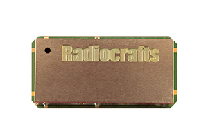
Product Details
The Wireless M-Bus RF Transceiver Modules are compact surface-mounted high performance modules with embedded Wireless M-Bus protocol. The RC11xx series covers 868 MHz, as well as variants at 433, 865, 869, and 815/923 MHz. The RC17xx series covers 169 MHz. However, both the MBUS3 and MBUS4 modules can be configured to operate as Slave (in the meter), Master (in the concentrator), or as Repeater (single hop).
The modules (MBUS3, MBUS4) have an easy to use UART interface for serial communication and configuration and a one-pin antenna connection. Furthermore, when used with quarter-wave antennas, a line-of-sight range of over 800 meters can be achieved at 868 MHz, and several km at 169 MHz. Ultra-low power mode extends battery lifetime.
Similarly, the WIZE variant is based on the Wireless M-Bus N mode and is specially designed for deployments where the devices/sensors are located in hard-to-reach places: smart metering, public lighting, energy management of buildings, smart mobility, etc.
The MPC1 (M-Bus Pulse Counter) variant contains an autonomous application for pulse counting, alarm supervision and transmission scheduling. Also, it supports over-the-air configuration and installation.
- Full feature Wireless M-Bus stack embedded
- EN 13757-3:2013, EN 13757-4:2013 and EN13757-5:2013
- 868 MHz (C,R,S,T modes) and 169 MHz (N mode)
- 433, 865, 869, 915, 923 MHz for non-EU operation
- Master module up to 256 slaves
- Auto-message generator
- AES-128 hardware encryption
- Designed for Open Meater Reading (OMS) specification
- Designed for NTA8130/DSMR/SMR
- Special support for CIG (Italy) TS 11291-11-4
- UART interface for communication and configuration
- Pulse counter and automatically scheduled transmissions (MPC variant)
- Ultra low power modes for battery lifetime > 15 years
- High power option (27/30 dBm) in same footprint
- Compact shielded module 12.7 x 25.4 x 3.3 mm for SMD mounting
- Designed for CE compliance
Configuring a Wireless M-BUS Network
A Wireless M-Bus network is very easy to configure, if configuration is needed at all. In the simplest case, the Meters are one-way transmitters, and the Concentrator or Reader is the receiver. The receiver can in principle receive data from any meter sending a valid Wireless M-Bus message or the receiver can register the unique addresses of each meter and filter the data based on this. In addition, data encryption will ensure data privacy and integrity, preventing data to be understood or manipulated even if the message can be received by any radio.
Each meter has a unique 8 byte ID or address. In general, the address consists of a Manufacturer ID, a serial number, the device type (e.g. water meter) and the version of the meter. In this way each manufacturer can ensure that every meter deployed in the field has unique addresses.
The Wireless M-Bus protocol was invented and developed for battery operated meters. Hence, it is optimized for very low power consumption, even for two way communication. The achieve this, the meter provides a short reception window after the message transmission. In this case, the concentrator should make a transmission to the meter within this short time window. Any command to a meter, must therefore be prepared and sent exactly when the meters own receiver is turned on. In fact, Radiocrafts has patented solutions for how this is handled autonomously by a radio module in the concentrator. Because the communication is encrypted, messages must be decrypted and encrypted as part of the time critical communication sequence. This is solved by an intelligent and configurable message generator and mailbox system within the radio module.
Wireless M-Bus also allows for Repeaters. For example, the MBUS3 implementation contains single-hop repeater functionality. When the module is configured as a Repeater, it will receive data from any meter, and re-transmit the message after a few seconds. Then, the repeated message is marked with a flag, so that it will not be repeated a second time, avoiding endless repetition loops in the network.
Our MBUS modules are easily configured using the MBUS-DEMO tool. To clarify, this PC tool also includes a packet sniffer and packet generator simplifying laboratory tests. Additionally, all configurations and data communication are done over a UART interface.
Using the Radiocrafts Wireless M-Bus module makes it easy to generate a valid M-Bus packet. When the module has been configured for the desired mode (T, S, C etc) and device type (e.g. as Slave for use in a meter), simply send the application layer data string preceded by a length byte. After that, the module will add the rest of the protocol used in the radio transmission, and even do the data encryption if desired.
DATA SHEETS AND USER MANUALS
File type: |
File name: |
File description: |
|---|---|---|
Shortform datasheet for the RC1701HP-WIZE module. |
||
This document covers the relevant information for the RC1701HP-WIZE module, such as product features, reference data, circuit and pin description, module configuration, power supply, programming interface, antenna connection and other product related information. |
||
This document is a short form version of the data sheet of the wireless modules with Pulse Counter inputs. It includes the preliminary information of the product, such as features, specifications, pin description and assignment. |
||
This document covers the relevant information about the RC11X0-MBUS module series, such as product features, reference data, circuit and pin description, MCU considerations, power supply, programming interface, antenna connection ant other product related information. |
||
This document covers the relevant information about the RC1180-MBUS3 module, such as product features, reference data, circuit and pin description, MCU considerations, power supply, programming interface, antenna connection ant other product related information. |
||
This document covers the relevant information on the RC1180HP-MBUS3 module, such as product features, reference data, circuit and pin description, module configuration, power supply, programming interface, antenna connection and other product related information. |
||
This document covers the relevant information about the RC1180-MSM module, such as product features, reference data, circuit and pin description, MCU considerations, power supply, programming interface, antenna connection ant other product related information. |
||
This document covers the relevant information about the RC1701XX-MBUS module series, such as product features, reference data, circuit and pin description, MCU considerations, power supply, programming interface, antenna connection ant other product related information. |
||
This document covers the relevant information about the RC1701HP-MSM module series, such as product features, reference data, circuit and pin description, MCU considerations, power supply, programming interface, antenna connection ant other product related information. |
||
User Manual for WIZE modules is a step by step introduction how to use our module with the WIZE Protocol. The document describes the WIZE feature sets, basic functionality, timing, power management, installation and binding, 2-way communication, and more. |
||
User Manual for Wireless M-Bus modules is a step by step introduction how to use our module with the MBUS protocol. The document describes the MBUS feature sets, Wireless M-BUS embedded protocol, the UART interface and timing, power management and supply voltage. The document also includes the descriptions of the MBUS1, MBUS2, MBUS3 and MBUS4 protocols. |
||
User Manual for The MPC1 Wireless M-Bus module with the pulse counter inputs, which is based on the MBUS3/MBUS4 protocol. The document describes the pulse input, installation, over the air configuration, pin assignment and description, configuration memory and quick demo. |
||
User Manual for Wireless M-Bus Sensor Modules modules is a step by step introduction how to use our module with the MBUS protocol. The document describes the MBUS feature sets, Wireless M-BUS embedded protocol, the UART interface and timing, power management and supply voltage. The document also includes the descriptions of the MBUS1, MBUS2, MBUS3 and MBUS4 protocols. |
APPLICATION NOTES
File type: |
File name: |
File description: |
|---|---|---|
Different applications and different use-cases will need different wireless connectivity technologies. Therefore, selecting the right wireless technology is a critical design decision. Based on radio performance requirements and other criteria, this selection guide will point out the differences between the technologies to help selecting the right one. |
||
This is a short Application Note on the use of license free RF modules in New Zealand, and in particular which modules from Radiocrafts will meet the local radio regulations. |
||
Utility metering systems handle billing information for high value commodities, and demand control makes it also a part of the critical infrastructure. The security of such systems is of the highest importance. The integrity of data transfer, in the case of meter communication (and switch or valve control) may also be a safety issue as well. It used to be a matter of tamper protection, but with the use of automatic and remote meter reading (smart metering), the focus is on communication security. |
||
The Wireless M-Bus standard (actually a European Norm, EN 13757-4) is a wireless communication protocol that was developed for the reading of electricity, gas-, water-, heat-meters and heat allocators. It has gradually been extended as new frequency bands and technologies have become available. The mode N (“Narrowband”) was added when the 169 MHz band was opened for license free use for utility meter reading. A new major addition and revision of the EN 13757-4 standard related to mode N was done in the 2019 release. This Application Note gives an overview of the M-Bus standard documents and summarizes the main changes in this new release of part -4. |
||
There are many different wireless standards and technologies available to enable the internet of things (IoT). The different technologies have different pro’s and con’s depending on the use case and the end customer. Trying to keep up with the latest wireless trends can drain a company of all its resources and take attention from its core business. The solution recommended by Radiocrafts is to use a modular approach and a common RF module footprint that enables all the technologies offered by Radiocrafts without modifications to the PCB. |
||
Making a good RF antenna is by some considered a challenging part of a wireless product design. It required RF knowledge which is not common among general electrical design engineer and not widespread know-how among software engineers either. Radiocrafts has developed a process and the tools required to make this tuning process simple and straightforward in a way that a person with no RF experience can tune a 169MHz antenna to the final product. |
||
Wireless M-Bus (EN 13757-4:2013) is a wireless communication standard that was developed for the reading of electricity, gas-, water-, heat-meters and heat allocators. However, the reading of utility meters is very similar to applications in the industry where sensors or actuators need to be read or operated at a distance. All the issues have already been addressed in the development of the Wireless M-Bus standard. |
||
When selecting the right radio technology, the achievable communication range is an important factor. This document review how to analyse radio range based on parameter provided in the data sheets for the different module families. Some measurement results from practical range testing are also shown |
||
The purpose of this document is to list some of the most common issues that customers report when using Radiocrafts modules, and the solution to these issues. |
||
The Italian “CIG Interchangeability Task Force” has published UNI/TS 11291-11-4, Gas measurement systems – Hourly based gas metering systems, Part 11-4, Communication profile PM1. This application note points out how the RC1701HP/VHP-MBUS4 module can be used to meet the requirements of this companion standard. |
||
Radiocrafts offers a wide range of wireless modules targeting different solutions word-wide. This Application Note informs how to select and use Radiocrafts modules for FCC compliance in US. |
||
This Application Note describes how the Wireless M-Bus modules (MBUS3, MBUS4) from Radiocrafts can be enabled with CRC-16 for possible error identification on the UART port. This feature secures that the data handling on the serial interface is more secure as wrong data can be rejected. |
||
“The Radiocrafts Demo Boards and USB-sticks include an on-board firmware upgrade connector compatible with different flash programming adapters. It is also recommended that PCB layouts include a connector for firmware upgrade. This Application Note describes how to upgrade the firmware of any Radiocrafts RFmodule using either a CC Debugger or the FlashPro-CC tools.” |
||
This Application Note describes how the Bridge (ref “Dongle” in figure 1) can be implemented with the RC1180-MBUS module. In some cases, the Bridge is located in an electricity meter which acts as a concentrator for one or more gas-, water and/or heat-meters. |
||
Wireless M-Bus (EN 13757-4:2013) is the only European Standard specifically targeting wireless reading of electricity, gas-, water-, heat-meters and heat allocators. The Radiocrafts module MBUSx and MPC1 is dedicated to these specific applications. This Application Note will help selecting the correct module for your Wireless M-bus implementation and informs you were to find more detailed information. |
||
The RC1xx0 and RC2x00 series of RF Modules with integrated protocol offers easy adaptation of wireless communication utilizing a simple UART serial interface. In their standard versions without any required configuration the modules offer two pins for controlling PA, LNA and SPDTs for signal switching. Two SPDTs are required since it is only one RF pin on the Radiocrafts modules. |
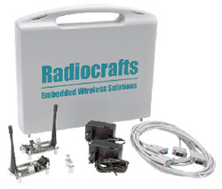
For all our Wireless M-Bus modules, Development Kit suitcases are available for rapid prototyping and proof of concept. The kits contain:
- Two Development Boards with the module of choice, onboard USB level shifter and USB connector, SMA antenna connector, I/O break-out
- Quarterwave stub antennas with SMA connector
- USB cables
- The HP variants include additionally AC/DC Power Supplies
One kit will make a wireless link “out of the box” and feature easy access to all the modules I/O-pins. The kit can be used together with the PC software tools.
File type: |
File name: |
File description: |
|---|---|---|
The Demonstration Kit from Radiocrafts is designed to make it easy for the user to evaluate the module, develop an application and build prototypes. Bundled with the Demonstration Kit is the RCTools PC software to be used together with the Demo Boards. |
||
The Demonstration Kit from Radiocrafts is designed to make it easy for the user to evaluate the module, develop an application and build prototypes. Bundled with the Demonstration Kit is the RCTools PC software to be used together with the Demo Boards. |
||
This User Manual describes how to use the Demonstration Kit for RC11xx; RC12xx; RC2xxx module series and provides detailed documentation for the Demonstration Board. |
||
This User Manual describes how to use the Demonstration Kit for RC11xxHP; RC12xxHP; RC17xxHP module series and provides detailed documentation for the Demonstration Board. |
Tools & Manuals
File type: |
File name: |
File description: |
|---|---|---|
RCTools is a powerful and easy to use PC suite that helps you during test, development and deployment of the Radiocrafts modules. The RCTools includes RC_CCT, RC_SA and RC_DT stand-alone applications running under windows .Net Framework. The RCTools is free of charge and easily installed (including .NET and USB Driver) by running the setup file. |
||
RC Tools-MBUS contains the PC tools for design with the Wireless MBUS family. It includes the CCT tool and the Demo tool. |
||
This is s a software suite containing tool for easy module configuration and concentrator/meter emulators. The tool helps you transmit encrypted Wireless M-Bus packets, set up two-way communication, and provides a packet sniffer. |
||
The MBUS-CCT (Configuration & Communication Tool) helps you to work with your Radiocrafts modules. The program enables you to easily configure the module and can additionally work as a terminal window, where data can be sent or received to / from any serial port. The RSSI (Received Signal Strength Indicator) informs you about the Link budget and helps you estimate range. |

What is Wireless M-Bus?
Wireless M-Bus is the only European standard (norm) for wireless meter reading (EN 13757). The standard was originally developed for communication with battery operated gas, water and heat meters, operating at 868 MHz with a focus on low power consumption and low implementation cost. Later, the standard was updated and expanded to include narrowband radio, security (encryption and authentication), and repeater networks. Moreover, it supports all types of utility meters as well as environmental sensors. In particular, Wireless M-Bus is the basis for OMS (Open Metering System) and other national companion standards (France, Italy, Netherlands) for meter reading.

For any module inquiries please contact our local partner.
Or buy online at Digikey.com
Product Name | Frequency | Region Compliant | Buy Module Online | Buy Development Kit Online |
RC1140-MBUS3 | 433 MHz | OMS / non-EU | ||
RC1160-MBUS3 | 868 MHz | OMS / Russia | Contact Radiocrafts | |
RC1170-MBUS3 | 865 MHz | OMS / India | Contact Radiocrafts | |
RC1170HP-MBUS3 | 865 MHz | OMS / India | ||
RC1180-MBUS3 | 868 MHz | OMS / EU / CE | ||
RC1180HP-MBUS3 | 868 MHz | OMS / EU /CE | ||
RC1701HP-MBUS4 | 169 MHz | EU / CE | ||
RC1701VHP-MBUS4 | 169 MHz | EU / CE | Contact Radiocrafts | |
RC1701HP-WIZE | 169 MHz | EU / CE | ||
RC1140-MPC1 | 433 MHz | non-EU | ||
RC1170-MPC1 | 865 MHz | India | Contact Radiocrafts | |
RC1180-MPC1 | 868 MHz | EU / CE | ||
RC1701HP-MPC1 | 169 MHz | EU / CE |